
Eight categories 18 kinds of hydraulic valve detailed explanation, with 38 GIFs!
Hydraulic valve: is an automatic component operated with pressure oil, controlled by pressure valve pressure oil, usually combined with electromagnetic pressure valve, can be used for remote control of hydropower station oil, gas, water pipe system.
Classification by control method: manual, electronic control, hydraulic control
Classification by function: flow valve (throttle valve, speed regulating valve, shunt collecting valve), pressure valve (relief valve, pressure reducing valve, sequence valve, unloading valve), direction valve (electromagnetic reversing valve, manual reversing valve, check valve, hydraulic control check valve)
1 Check valve (2 types)
The check valve is that the fluid can only flow along the inlet, and the outlet medium can not return, commonly known as the check valve.
Check valve is also called check valve or check valve. Used to prevent the reverse flow of oil in hydraulic systems, or to prevent the reverse flow of compressed air in pneumatic systems
When installing the check valve, special attention should be paid to the flow direction of the medium, and the normal flow direction of the medium should be consistent with the direction of the arrow indicated on the valve body, otherwise the normal flow of the medium will be cut off. The bottom valve should be installed at the bottom of the water pump suction pipe.
When the check valve is closed, water hammer pressure will be generated in the pipeline, which will cause serious damage to the valve, pipeline or equipment, especially for the large mouth pipeline or high pressure pipeline, so the check valve should be paid attention to.When the check valve is closed, water hammer pressure will be generated in the pipeline, which will cause serious damage to the valve, pipeline or equipment, especially for the large mouth pipeline or high pressure pipeline, so the check valve should be paid attention to.
①Right Angle check valve

②Straight through check valve

Check valve A port inlet oil

Check valve B port inlet oil

Check valve has control oil
2 Reversing valve (4 types)
The reversing valve is a directional control valve with more than two flow forms and more than two oil ports. It is a valve that realizes the communication, cutting off and reversing of hydraulic oil flow, as well as pressure unloading and sequential action control.
This kind of change valve is widely used in petroleum and chemical production, and is most commonly used in synthetic ammonia gas making system. In addition, the reversing valve can also be made into a disc type structure, which is mostly used for small flow situations. When working, just turn the hand wheel through the valve disc to change the flow of the working fluid
Reversing valve ➞ two-position two-way:
Two means that the spool works in two states, when the coil is not energized, the spool is in one position, when energized, it moves to another position, and the on-state of the valve is switched by changing the position; Two-way means that the valve has two ports(one in and one out).
The two-position two-way valve is actually a stop valve, the purpose of starting and closing/opening the pipeline, there is no reversing function.

Reversing valve ➞ two position four way
Two four- way directional valve is suitable for dry oil or thin oil centralized lubrication system to change the direction of oil supply or
open and close the oil supply pipeline.
The reversing valve is driven by a high-torque DC gear motor, so the reversing action is reliable even under harsh working conditions, such as low temperatures or very viscous greases.
During the reversing process, the piston runs at a high speed in a very short period of time, reducing reciprocation and thus avoiding premature wear.
When receiving the commutation signal in the system, the DC motor rotates and converts the rotating motion into the linear reciprocating motion of the piston rod through the eccentric wheel. When the piston moves from one end to the other end and reaches the required commutation position, the limit switch acts to make the DC motor lose power, and then the motor stops rotating and the commutation process is completed.

Reversing valve - two position four way left

Reversing valve - two position four way right
Reversing valve ➞ three position four way
P is the oil supply port, O is the oil return port, and A and B are the output outlets leading to the actuator.
When the spool is in the middle position, all the oil ports are cut off, and the actuator does not move;
When the spool is moved to the right position, P is connected to A, B is connected to O;
When the spool is moved to the left position, P is connected to B, and A is connected to O.
In this way, the actuator can move forward and backward.
Reversing valve ➞ three position four way left

Reversing valve ➞ three position four way middle
Reversing valve ➞ three position four way right
Reversing valve ➞ three position five way

Reversing valve ➞ three position five way left

Reversing valve ➞ three position five way middle

Reversing valve ➞ three position five way right
3 Manual reversing valve (1 type)
The manual reversing valve is a directional control valve that relies on the action of the manual lever to drive the spool movement to realize the oil circuit opening and closing or switching.
The role of the manual reversing valve in the hydraulic system is the same as that of the electromagnetic reversing valve. It is easy to operate, reliable and does not require electricity.

4 Throttle valve (1 type)
A throttle valve is a valve that controls the flow of fluid by changing the throttle section or length.
The throttle valve has no negative flow feedback function and cannot compensate for the speed instability caused by the load change, which is generally only used for occasions where the load changes little or the speed stability is not required.
The shape structure of the throttle valve is no different from that of the globe valve, but the shape of their opening and closing parts is different. The opening and closing parts of the throttle valve are mostly conical and streamlined, through which the cross-sectional area of the channel is changed
to adjust the flow rate and pressure. The throttle valve is used to reduce the medium pressure in the case of extreme pressure drop.
The flow rate of the medium between the throttle disc and the seat is very high, so that the surface of these parts is quickly damaged - the so-called cavitation phenomenon. In order to minimize the impact of cavitation, the valve disc is made of cavitation resistant material (alloy steel) and made into a streamlined cone with a center Angle of 140 to 180, which can also enable the valve disc to have a larger opening height, and it is generally not recommended to throttle under small cracks.

Throttle valve

When the throttle opening is large

When the throttle opening is small
5 Diverter collector valve (1 type)
Shunt valve, also known as synchronous valve, is an independent hydraulic device that integrates the functions of hydraulic shunt valve and flow valve.
Usually there are many ways to realize synchronous movement, but the synchronous control hydraulic system using the shunt collector valve - synchronous valve has many advantages such as simple structure, low cost, easy manufacturing and strong reliability, so the synchronous valve has been widely used in the hydraulic system.

Diverter collector valve P3>P4

Diverter collector valve P3=P4
Diverter collector valve P3<P4
6 Sequence valves (4 types)
The sequence valve is a valve that controls the action sequence of the executive components according to the pressure of the circuit in a system with more than two branch circuits.
According to the different assembly structure, the sequence valve can achieve different loop functions, such as the function of the relief valve, the sequence valve and the balance valve.
If the opening and closing characteristics of the sequence valve are too poor, the primary pressure is too high when the flow rate is large, and the loop efficiency is reduced. The opening and closing characteristics have hysteresis, the opening pressure is lower than the closing pressure, and the load flow rate should be noted when changing.
Open the valve with too low pressure, and the front leakage occurs when the pressure is lower than the set pressure, causing the actuator to misoperate. When the flow rate through the valve is much less than the rated flow rate, vibration or other instability occurs. Take action on the way back.
①Internal control internal drain type sequence valve

②Internally controlled leakage type sequence valve
③External control internal drain type sequence valve
④Externally controlled leakage type sequence valve

7 Speed regulating valve (1 type)
The speed regulating valve is composed of a pressure reducing valve with a fixed difference and a throttle valve in series, and is a throttle valve with pressure compensation.
The throttle valve is used to adjust the flow through, and the fixed-difference pressure reducing valve automatically compensates the influence of the
load change, so that the pressure difference before and after the throttle valve is a fixed value, eliminating the influence of load change on the flow.
The pressure before and after the throttle valve is led to the right and left ends of the pressure reducing valve spool respectively. When the load pressure increases, the liquid pressure acting on the left end of the pressure reducing valve spool increases, the valve spool moves right, the pressure relief port increases, and the pressure drop decreases, so that the pressure difference of the throttle valve (p2p3) remains unchanged; And vice versa. In this way, the flow rate of the speed control valve is constant (not affected by the load).
The speed regulating valve can also be designed to throttle before reducing pressure.

When the pressure of the governor valve is reduced
When the pressure of the governor valve rises
8 Relief valve (4 types)
Relief valve is a hydraulic pressure control valve, which mainly plays the role of constant pressure relief, pressure regulation, system unloading and safety protection in hydraulic equipment.
Constant pressure overflow effect: In the quantitative pump throttling regulation system, the quantitative pump provides a constant flow rate. When the system pressure increases, the flow demand will decrease. At this time, the relief valve is opened, so that the excess flow flows back to the tank, to ensure that the relief valve inlet pressure, that is, the pump outlet pressure is constant (the valve port is often opened with pressure fluctuations).
Pressure stabilizing effect: The relief valve is connected in series on the return oil circuit, the relief valve produces back pressure, and the stability of the moving parts is increased.
System unloading function: the remote control port of the relief valve is connected to the solenoid valve with a small overflow flow. When the electromagnet is energized, the remote control port of the relief valve passes through the fuel tank, and the hydraulic pump is unloaded at this time. The relief valve is now used as a unloading valve.
Safety protection: When the system is working normally, the valve is closed. Only when the load exceeds the specified limit (system pressure exceeds the set pressure), the overflow is turned on for overload protection, so that the system pressure is no longer increased (usually the set pressure of the relief valve is 10% to 20% higher than the maximum working pressure of the system).
The main requirements for the relief valve are: large pressure regulation range, small pressure regulation deviation, small pressure oscillation, sensitive action, large overload capacity, and small noise.
Pilot operated relief valve
The pilot type relief valve, acting on the main spool and the pilot spool pressure measuring surface, is composed of the pilot and the main valve.
When working, the liquid pressure acts on the pressure measuring surface of the main spool and the pilot spool simultaneously.
When the pilot valve 1 is not opened, the oil does not flow in the valve chamber, and the pressure acting on the main spool 6 is equal in both directions, but because the effective pressure area A2 of the upper end is greater than the effective pressure area A1 of the lower end, the main spool is in the bottom position under the action of the resultant force, and the valve port is closed.
When the inlet pressure increases enough to open the pilot valve, the liquid flows through the damping hole on the main valve spool 5, pilot valve 1 flow back to the tank. Due to the damping effect of the damping hole, the liquid pressure in the upper and lower directions of the main spool 6 is not equal, and the main spool moves upward under the action of the pressure difference, opens the valve port, realizes the overflow, and maintains the basic stability of the pressure. The overflow pressure can be adjusted by adjusting the pressure regulating spring 9 of the pilot valve.

Pilot operated relief valve

The relief valve is overflowing
When the inlet pressure is not high

When the oil inlet pressure rises
Low pressure relief valve

When the inlet pressure is not high
When the oil inlet pressure rises
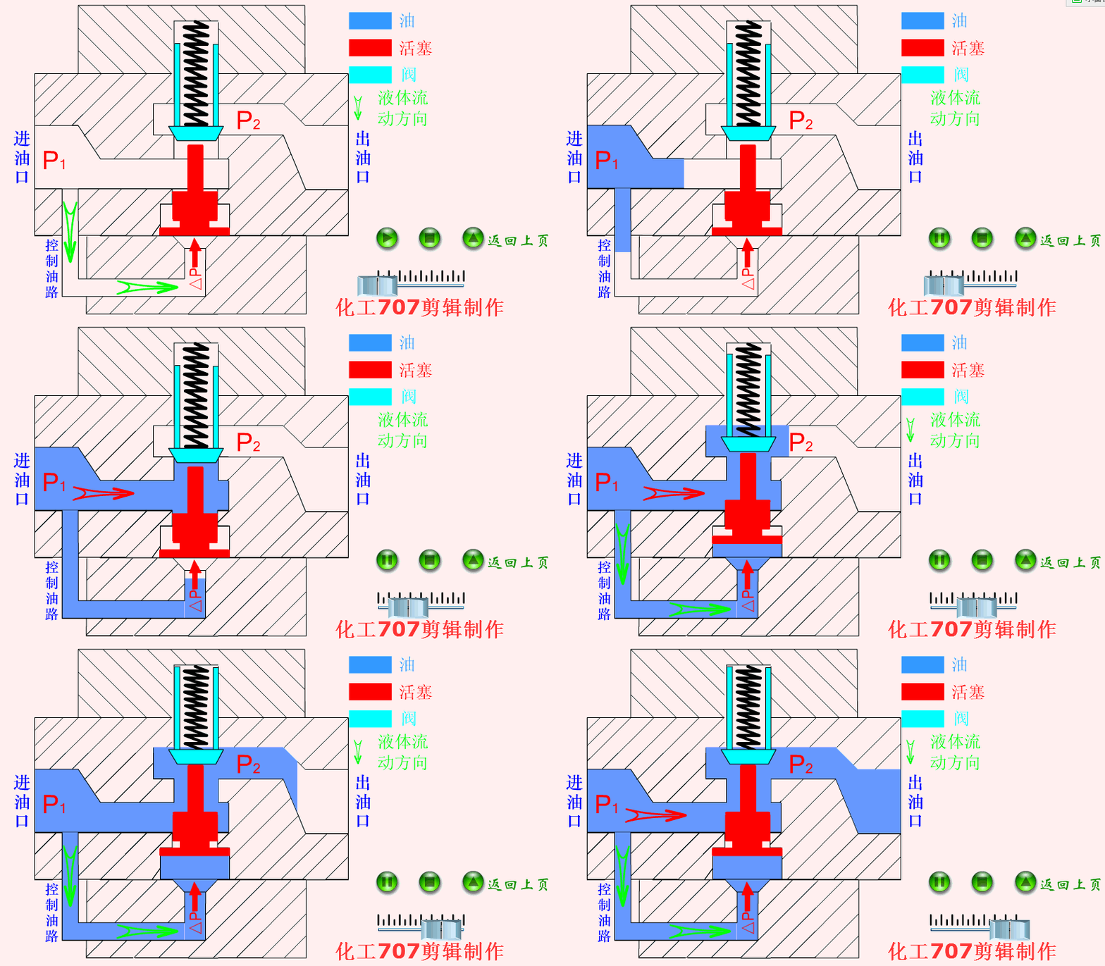
Reducing valve
The pressure reducing valve is a valve that reduces the inlet pressure to a certain required outlet pressure by adjusting it, and relies on the energy of the medium itself to keep the outlet pressure stable automatically.
From the fluid mechanics point of view, the pressure reducing valve is a local resistance can change the throttling element, that is, by changing the throttling area, the flow rate and the kinetic energy of the fluid change, resulting in different pressure losses, so as to achieve the purpose of decompression.
Then rely on the adjustment of the control and adjustment system, so that the fluctuation of the pressure after the valve is balanced with the spring force, so that the pressure after the valve is kept constant within a certain error range.
Cartridge valve
Cartridge valve is different from the ordinary hydraulic control valve we say, its flow rate can reach 1000L/min, and the diameter can reach 200 ~ 250mm.
The spool has simple structure, sensitive action and good sealing. Its function is relatively single, mainly to achieve the liquid circuit on or off, and the combination of ordinary hydraulic control valve, in order to achieve the direction of the system oil, pressure and flow control.